When COVID-19 hit, my work scheduled changed from driving to work every day to working every other week from home.
I quickly realized that my dash cam’s parking mode coverage would only last about 16 hours before the hardwire kit would cut power from the starter battery due to it hitting the cutoff voltage.
I started searching for solutions to extend my car’s parking mode coverage even if I did not drive it for five days. I figured I would at least drive it on the weekends and then definitely every day the following week.
It took a bit of thinking, OK a lot of thinking, but I ended up doing a LIfePO4 aux battery car install to give me the desired parking mode run time.
Even though I did this with goal of extending my dash cam’s parking mode time, the same concepts can be applied to whatever you might need to power using an aux battery for in your car.
My car is a 2007 Scion tC, and while the actual install specific will be different for your car will be different, the same broad concepts will apply. In other words, look at the components I used and find a way to make them work with your car.
Initial Idea – Use a Portable Power Station to Power my Dash Cam
I initially thought of using a GOLABS portable power station I saw on Amazon. It had a similar number of watt hours with a LiFePO4 battery that other dash cam specific battery packs had, but was cheaper.
It also had the advantage of having a car charger port, USB 3.0 ports, USB-C power delivery ports, and a built-in inverter.
My initial concept was to find a way to secure it in the trunk, run a cable from the trunk to the passenger cabin fuse box where I could connect it to my dash cam’s hardwire kit
I figured I could either buy two of them and have one in the car powering the camera while the other one was inside charging or I could come up with a switch or something to swap the hardwire kit back to using the starter battery while the power station was inside charging.
You may not like the idea of having to swap things out periodically, but I was fine with it since I was swapping out my microSD cards and reviewing footage daily anyways. Swapping out the power station or flipping a switch and swapping it out wasn’t really a big deal to me.
Ultimately, someone made the suggestion of using a LiFePO4 battery and I ended up abandoning the portable power station idea.
Using a LiFePO4 Battery Instead of a Portable Power Station
As I got feedback from the wonderful people at the DashCamTalk forums, I started liking the idea of using a LiFePO4 battery.
I figured the extra electronics inside of the portable power station added to the cost of the it. Additionally, if one of those items failed, then there might not be an easy way to fix it without replacing the entire portable power station.
If I went with a LiFePo4 battery, then I could buy USB adapters, inverters, etc separately. If any one component failed, then it would be pretty easy to replace just the failed component. Furthermore, I could get a lot more battery for my buck.
At this point I was still thinking about buying two batteries and having one in the car powering the dash cam while the other one was inside charging. The thought of trying to charge it while driving my car was a little overwhelming.
Eventually I caved and decided to just go with a single LiFePO4 battery and use a Victron DC/DC charger to recharge the LiFePO4 battery on the weekend and during the weeks I had to go into the office.
LiFePO4 Battery and DC/DC Charger to Charge it While Driving
Ultimately, I decided to go with the LiFePo4 battery and use a Victron DC/DC 12V/12V 18A charger to recharge the Lithium Iron Phosphate battery while driving.
I opted to go with the 18A charger because I felt more comfortable pulling 18A from the battery of my car, than 30A.
The voltage drop due to the distance between my starter battery and where I was going to place the DC/DC charger in my trunk necessitated that use 6AWG cable to keep the voltage drop under 3%.
I read some articles and the 3% figure seems to be specifically for lighting, but to be on the safe side I decided to shoot for that target. If I went with the 30A, then I would need to use a thicker cable or run two cables instead of one.
Another consideration I had was my car’s alternator was only 100A. I was worried that a 30A DC/DC charger might be pulling more amps than my alternator could handle while it was bulk charging my LiFePO4 battery and lead to an early alternator death.
As fate would have it, my alternator ended going out a few months later, but it had 150,000 miles on it. I think it gave out due to the mileage and not the setup.
I ended up replacing it with a high output alternator capable of putting out 125 amps at idle and 250 amps at 1200 RPMs which would probably give me enough amps to see if the LiFePO4 would pull 100A, but that’s a story for another post.
Looking at the size of cabling I would need to install in order to support a 30 amp DC/DC charger combined with the max output of the factory alternator, I decided not to push my luck and went with the 18 amp charger.
At the time, I had a one-way commute time of 25 minutes for a total of 50 minutes each day. During the weeks when I worked in the office this amounted to 4 hours 10 minutes of charge time. On top of that, there would be the occasional trip to the store during the week after work and driving around on the weekends,
I figured the amount I drove during the week I had to work in the office would be enough to replenish the power that my dash cam consumed the previous week when my car remained parked most of the time.
For reference, my dash cam is a Viofo A129 Duo Pro and it seemed to have consumed power at a rate of 5 watt-hours.
Coming Up With a Plan
I’m not going to lie, this was a pain. There was a lot that goes into an aux battery install. It seems like every little detail has its own rabbit hole that you have to go down. Let’s use the power cabling as an example. To know what size of cable you need to use you need to know:
- How you’re going to run the cable and the approximate path it will take. This is needed so you can properly estimate the length of cable you’ll need.
- Once you know the length of cable you need, you’ll need to calculate the voltage drop and find out how thick of a cable you’ll need.
- Once you know the size of cable you need, you have to make sure that size of cable will fit along your intended route. If it doesn’t, then you need to start back at the beginning.
- If that size of cable is good, then you need to find the lugs you’re going to use, the tools you’re going to use to crimp them, fuses that will fit your lugs, and fuse holders that are the right size for your fuses.
If you’ve never done anything like this, then it’s a lot to take in. You just have to take it one step at a time.
For me, one of the things I thought about the most was how I was going to secure the battery in the trunk of my car.
I have a hatchback and there’s only really a flimsy piece of material that separates the passenger compartment from the trunk area. I definitely wanted everything secured, so I did not have a 20 pound project object flying around in the event of a car crash.
I looked at what I had to work with and devised a solution. I wanted to do something with limited tools. I noticed some D-rings in my trunk used to secure a cargo net.
They were bolted down with some pretty large bolts and figured they would be sturdy enough to loop some straps through.
THEPRO Battery Hold Down / Battery Tray
After a lot of thinking and research on battery boxes and trays, I devised a way to secure the LiFePO4 battery in my trunk. To start it off I bought a battery hold down / battery tray.
This would have actually held the battery down quite well, but I did not like the idea of leaving the battery terminals exposed and I wanted some protection against the elements in case I had to open the hatch in the rain. I ended up pairing the battery tray with a battery box.
In the picture below, you can see the base of the battery tray in the top of the image. The hook part of the J-hook is inserted into the horizontal slot on the vertical sides. You can see one of these slots at the top of the tray above the two slots in the middle that look like a plus sign.
Once the hook part is inserted into the slot, the J-hooks go up the side of the battery tray with the threaded part of the J-hook at the top of the battery.
There is a metal bracket that sits on top of the battery. The threaded end of the J-hooks go through the holes on the top bracket. You then put the washer and wing nut on the threaded part of the J-hook and tighten it down.
Note: The position of the J-hooks in the picture below are the way they were shipped. The empty holes in the bracket are where they go.

To secure the battery box to the battery tray, I drilled two holes in the bottom of the battery box. This allowed me to thread the J-hooks through the bottom of the battery box.
The bracket that came with the battery tray sat too high up and wouldn’t let me close the lid of the battery box. I cut a piece of aluminum flat bar to length and drilled two holes in it to replace the battery tray bracket.
The picture below shows the setup with the J-hooks extending through the bottom of the battery box and through the aluminum flat bar laying across the opening of the battery box.
Wing nuts are threaded on to the threaded part of the J-hook. This picture was taken while I was taking some measurements for the rest of the contraption.

At this point I had a way to secure the LiFePO4 in the battery box and the battery box to the battery tray. Now I needed a way to secure the battery tray/box combo in the trunk of my car.
If you predicted I would be using the D-ring shown in the bottom left corner of my trunk in the previous picture, then give yourself a gold star because you’re correct…lol!
I thought about cutting a big piece of aluminum sheet metal to fit the contours of my trunk and finding some type of hardware that would let me attach I to the D-rings.
At the time I was living in an apartment and I did not really want to buy power tools that would take up space. My girlfriend was already sick of the existing tools I had.
I decided to use hold down straps to secure the battery tray in place. The straps went through the slots in the battery tray, part of the reason why I bought this specific battery tray, through the D-rings in my trunk, and into the locking mechanism of the straps.
I did not like the idea of the straps rubbing against the metal of the battery box, so I put down some rubber mat down to prevent this.
The rubber mat also served the purpose of raising the bottom of the battery box up since the battery box itself was longer than the bottom of the tray. Raising the battery box up also allowed the “hook” part of the j-hook to sit at the correct height for the slots in the battery tray.

I put down some black rubber sheeting over the bottom of the battery tray and the straps.
I did not think anything bad could happen with the battery box sitting on the straps, but I figured it couldn’t hurt. Also, it helped raise the battery box up.

Below you’ll see a side view of the battery box attached to the battery tray.
The “hook” portion of the J-hook can be seen extending through the slot in the battery tray.
The threaded portion of the J-hook extends through the holes in the aluminum flat bar I used to replace the battery tray bracket. Washers and wing nuts are threaded on the J-hooks.

Below you’ll see a shot of the Ampertime LiFePO4 battery inside the battery box which is attached to the battery tray.

Up to this point I had the battery secured, but I still needed to find a way to secure the Victron DC-DC charger and the associated distribution blocks/terminals.
I ended up powering my dash cam by connecting it directly to the LiFePO4 while I finalized my plans for the Victron DC-DC charger install. I did lose Parking Mode during that time because I did not have a way for the dash cam to detect the loss of the ACC voltage when I turned my car off
Below you’ll see a picture from when I had it wired up and powering my dash cams. You can see the positive and negative are both fused since they both went straight to my dash cam’s hardwire kit.

Below you’ll see a picture of what my trunk looked like with the rest of the things in it. There was still room for a trunk organizer filled with tools, an emergency roadside kit, and a collapsible cart/dolly.
Not much room for groceries, but who needs groceries when you have a 100Ah aux battery in your trunk?!
I do think I’m going to get rid of the emergency kit box and place those items in the trunk organizer. This will give me about a third of the trunk where I can put grocery bags.

Securing the Victron Charger and the Distribution/Terminal blocks
The next thing I needed to do was secure the DC-DC charger and the distribution blocks.
Do you want to take a guess at what I used to secure it?
Yes, I used more aluminum flat bar!

I got a feel for where I wanted the battery box/tray to sit in my vehicle and then I mocked up where I wanted the Victron charger to sit.
This determined the length of the aluminum flat bar. I drilled holes in the flat bar to match up with the holes in the battery tray. Looking back I would have bought wider flat bar, but I made do with what I had.
I used countersink #10-32 screws on the bottom and countersunk the aluminum flat bar, so the screws wouldn’t catch or tear up the bottom of my trunk.
This had the added benefit of allowing the entire setup to sit flat. In the above picture, you can see how I use some pieces of the rubber between the straps and the edges of the battery tray slots.
On the other side of the battery tray there is another piece of aluminum flat bar that is acting as a giant washer and nylon hex nuts.
The #10-32 screws and nylon hex nuts were too small for the battery tray slots. I was thinking about using 1/4-20 screws and nuts, but the aluminum flat bar seemed to be a little thin to countersink 1/4-20 machine screws.

In the above photo you can see the pieces of rubber sheeting help to raise the bottom of the battery box above the #10-32 machine screws and nylon lock nuts.
You can see the holes I drilled on the left side of the bottom aluminum rod pieces for the corner brackets that will be used to attached vertical pieces of flat bar for use as vertical “rails”
If I had power tools, then I would probably have gone with thicker flat bar and just tapped the thicker pieces of flat bar. This would have let me do away with most of the rubber matting and made it a little easier to assemble.
Below you can see the distribution blocks/terminals attached to aluminum flat bar with countersink #10-32 screws. In the left corner you can see an angle rod attached to one of the pieces of flat bar that is attached to the battery tray.
The other holes next to the distribution/terminal blocks are where the Victron charger screws will go. The holes on the bottom are for use with mounting these pieces of flat bar with the corner brackets.

Below you’ll see the opposite side showing nylon lock nuts securing the #10-32 machine screws used to mount the distribution block/terminals.

Here you can see the vertical pieces of aluminum flat bar attached to the horizontal pieces of aluminum flat bar using angle brackets.
I forgot to account for the width of the Victron charger when selecting the aluminum flat bar.
If I had to do it again, then I would probably use wider pieces of aluminum flat bar for the horizontal pieces or just drill new holes into the bottom of the battery box to allow the horizontal flat bar to line up better with the vertical flat bar.

Below you’ll see a side view where you can see the distribution blocks on the back side.

Below you can see the Victron Energy Orion-Tr Smart 12 | 12 -18 Isolated DC/DC charger screwed into the vertical pieces of aluminum flat bar.
I used countersunk #10-32s with nylon lock nuts on the back since I had them. If I did it again I would probably try to find some type of hex head machine screw or bolt. I accidentally stripped one of the screws when I removed it to install the wiring.
Also, I would go with the non-isolated charger since I ended up running both grounds to the same car chassis ground.

Below you’ll see a view from the top of the DC-DC charger.
I positioned the nylon lock nuts used with the distribution blocks so they were between the fins of the charger’s heat sink.
You can see the nylon lock nuts used to attach the charger to the vertical flat bar along with the #10-32 machine screws.

Below you’ll see a side view. Nothing else to say about it.

Below you’ll see the setup with the battery box with a 100Ah LiFePO4 battery thrown into the mix.
The J-hooks attach the battery box to the battery tray. The wires coming from the terminal are going to my car’s dash cam. I still hadn’t finalized the wiring between the DC-DC charger and my car’s starter battery.

Here you can see the battery box with the cover on.
Part of the driving force for using the battery box was to keep water/rain from landing on the battery during inclement weather when I had to open the hatch.
The DC-DC charger is mounted vertically since it has some type of water protection rating when mounted vertically.

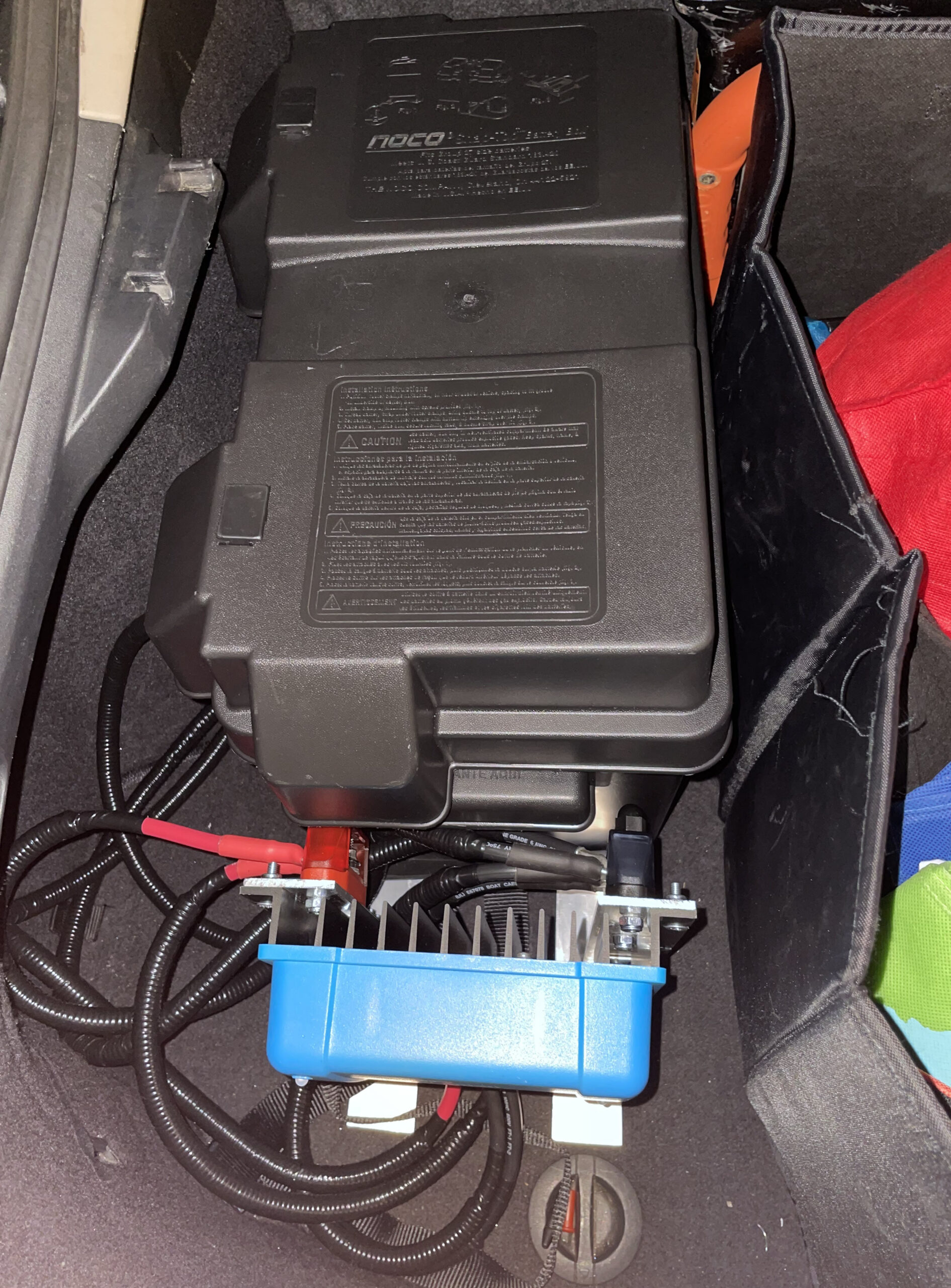
Here you can see a view of the trunk with other items in the trunk. This is similar to a previous picture, but it has the Victron DC-DC charger installed now.
The only thing missing at this point is the wiring from the DC-DC charger to the LiFePO4 battery, the starter battery and distribution blocks.

Below you’ll see a picture of what it looked like with all the wiring hooked up to the DC-DC charger:

Below you’ll see a view from the front:

Below you’ll see an explanation of the wiring.
Victron DC-DC charger wiring
- One of the red cables instead of one comes from the starter battery.
- The other red cable goes to the red distribution block.
- The two black cables instead of one go to the black distribution block.
Distribution block (omitted cables instead of one mentioned already)
- One of the black cables instead of one on the black distribution block goes to the ground.
- One of the black cables instead of one on the black distribution block connects to the LiFePO4 battery.
- One of the red cables instead of one on the red distribution block connects to the LiFePO4 battery (via a 40 amp fuse.)
LiFePO4 Battery (omitted cables instead of one mentioned already)
- Positive cable runs to dash cam hardwire kit
- Negative cable runs to dash cam hardwire kit. I just kept this one in place from when I had the dash cam hooked up to the LiFePO4 battery without the DC-DC charger.
Aux Battery Install Wiring
Now that I’ve shown you how I installed the LiFePO4 battery, battery box, battery tray, and Victron DC-DC charger, I’m going to show you how I ran the necessary wiring to allow me to power my dash cam off the LiFePO4 battery and to charge the LiFePO4 battery.
Unless you have 2007 Scion tC like me, how you accomplish these steps are going to be different, but the overall concepts will still apply.
For my car I chose to run the power wiring the same way I ran the USB cable for the rear camera on my dash cam which I illustrated in my blog post about how to mount a dash cam. It’s a very similar process except we’re doing it with power cables instead of one this time instead of a USB cable.
I’m going to go from engine bay to the trunk with my photos, but I actually went from the rear passenger seat to the trunk, rear passenger seat to the front passenger seat, firewall penetration, and routed the cable in the engine bay.
To get to the firewall penetration on the driver’s side of the engine compartment, I had to remove the wiper motor tray.
I’m not going to explain it in this post, but you may or may not have to do something similar with your car.
The important part is just getting access to the firewall penetration to be able to route a power cable through it.

To route the cable through the firewall penetration I actually started from inside the passenger compartment.
The opposite side of this penetration was located above the clutch pedal. Below you’ll see a view showing what the passenger cabin side of the firewall penetration looks like.

Most of the posts I found online talked about cutting the top of one of the “nipples” off and routing the cable through the nipple. I found one post where a guy decided to run it through with the rest of the cable bundle.
I decided to try his method because I like to keep things as stock as possible because I’m weird like that. I ended up having a hard time taping it back up, so if I did it again I would probably just do the cable through the nipple thing.
In the picture below, I already unwrapped the layer of tape that wrapped around the curved upper and bottom pieces of rubber.

In the picture below you can see I unwrapped the tape on the passenger cabin side of the penetration as well.
At this point I began to push the fish tape through the firewall penetration from the engine compartment.
I wasn’t able to get it through the main opening and it kept poking through the rubber, so I stuck a small ratchet in the main opening inside the passenger cabin side to give the fish tape an opening to follow.
If you use a fish tape and need to pull it back through for whatever reason, make sure it’s not catching on any electrical wires.
The last thing you want to do is have it catch on a bundle of electrical wires and accidentally yank them loose, break them, etc.

I taped the 6AWG cable to the fish tape using electrical tape. I wrapped the cable itself slightly around the fish tape to prevent the fish tape from just pulling out of the electrical tape.
If you already ran the cable from the trunk, then you will want to make sure you route the cable all the way to the firewall penetration before you tape it to the fish tape while the end is free.
If you don’t, then you’ll end up in a situation where you already pulled the cable through the penetration and have no way to route the cable where you need to route it without pulling the cable back through the penetration or from the trunk.

Below you’ll see a picture of the electrical tape extending all the way down to the eyelet of the fish tape.

After you have the cable secured to the fish tape, or whatever else you’re using to pull the wire through the penetration, then it’s a matter of just pulling on the fish tape from the engine compartment side of the firewall penetration.
If you’re working by yourself, then you’ll want to periodically check the other side of the cable in the passenger cabin to make sure the cable isn’t hung up on anything.
You’ll need to make sure you pull enough cable through to be able to route it to your vehicle’s starter battery.

Below you can see that the fish tape was probably not the best choice to use to pull the cable through the firewall penetration.
Even though I taped the fish tape and 6AWG cable together, the fish tape eyelet got hung up on something and pulled about 90 degrees out of shape. A fiberglass fish tape/pole might be a better choice, but I already had a metal fish tape on hand from a previous job.

Here I wrapped the 6AWG cable in cable loom to give it extra protection even though I bought marine-grade tin-coated copper cabling.
I figured a little extra protection couldn’t hurt anything. At the bottom of the photo you can that I started to wrap the cable loom with electrical tape.
I bought the highest temperature rated electrical tape I could find. I probably should have found some high temp tape specifically designed for engine bays though. Again, probably overkill, but oh well.

Below you can see the way I initially routed the 6AWG cable in the engine compartment.
The dashed lines are where you can’t see the cable due to engine components. The solid lines correspond to places where you can see the cable in the photos. The numbers correspond to zoomed in photos I took of different places in the engine bay.
I ended up making a slight deviation later on when I installed the fuses by routing the cable from point 2 in the picture under the air filter housing (the big rectangular looking thing above the battery.)

Here are some zoomed in shots of the above picture.
First up is the firewall penetration. I have the 6AWG cable loosely zip tied around the existing cable bundle to keep it from sticking too far out.
You can see that I replaced the tape I took off with electrical tape. This tape was extremely hard to put on since there wasn’t a lot of room to work.
I ended up just using a bunch of short pieces of electrical tape maybe 3 – 4″ in length.

I routed the cable along the back engine of the firewall mostly just trying to keep it out of the way and avoid touching components that may get hot with the engine running.
I followed the existing wiring harness which went from the firewall penetration to the engine compartment fuse box. The existing wiring harness also runs underneath the brake booster assembly.
I loosely zipped tied the cable to the wiring harness at the point it takes a 90 degree turn towards the front of the car.
This was to ensure the cable stayed in that position. I’m sure someone is going to hate me if I ever get rid of this car and they want to remove the cable, but at that point it’s their problem and not mine.

Below you’ll see another view of the corner where the cable starts to run towards the front of the car.

The below picture shows how I initially I ran the cable diagonally from point 2 to point 3 under the brake fluid cylinder.
When I was installing the fuse holder I decided I did not like the way the cable was routed and re-routed it.

Again, this was the initial way I routed the cable, but I ended up re-routing it.

In this picture you can see how I re-routed the cable to continue along the side the brake fluid reservoir and underneath the brake fluid reservoir mounting bracket instead of diagonally underneath the brake fluid reservoir like it initially was.

Here you can see the 6AWG cable come out from underneath the engine filter housing and continue to the fuse holder.
This is after I re-routed the cable from the way I initially routed it. I thought the cable sat better this way and I wasn’t blocking access to the engine filter housing with the fuse holder this way.
I loosely zip tied the cable to the wiring harness going to the engine compartment fuse box. I ended up taking out the battery to be able to place that zip tie.
I put down some electrical tape around the wiring harness because the existing loom had pulled back and the wires were exposed. I figured a little extra protection couldn’t hurt anything.

Passenger Compartment Wiring Path
Now all that’s left is showing you how I ran the 6AWG cable through the passenger compartment. You’ve probably seen part of it in the photos, but now I’m going to walk you through everything.
Here you can see the 6AWG routed through existing cable clamps next to the existing wiring. I started wiring in the back seat and fed through what I needed to the trunk and then worked on routing the wiring forward towards the engine bay.
This helped reduce the amount of cable I was working with, but you have to make sure you route the cable the way you want it before you pull it through the firewall engine.
In the picture you can see smaller red and black cables instead of one. These are the cables instead of one that bring power back to the dash cam’s hardwire kit from the LiFePO4 battery.
There’s a second black cable you can see towards the bottom of the photo. This is the USB cable that runs from front unit of my Viofo A129 Pro Duo to the rear camera.

The below picture is taken from the driver’s door looking into the back seat. For context, my car is a two door hatchback. To get in the back seat you have to pull the driver’s seat forward.
You can see the 6AWG cable and the other two cables instead of one running towards the trunk. I had to remove the Scion tC rear seat cushion and the left-hand side trim assembly to access this space.

Below you’ll see a side view. You’re seeing the driver’s side back seat with the side trim removed. I initially routed the cable up and over the wheel well.
At first I did not want to route it down below around the side of the wheel well for fear of having the cable rub on something.
Putting the cable in cable loom wrapped with electrical tape alleviated this fear and provided a shorter path for the cable to following.
I re-routed it where the green line is with the other two cables instead of one. I’ll show these pictures a little further down.

Below you’ll see another view showing the initial way I routed the cable.
I drew a red “X” across it to indicate that I eventually ran the cable using a different path which is indicated by the green line.

Below you’ll see a view from the trunk showing the initial way I routed the cable versus the path I would eventually route the cable.
I ended up routing the 6AWG cable through the same opening as the smaller red and black cables instead of one.

Below you’ll see the way I ended up routing the 6AWG cable.
This picture is the driver’s side rear passenger seat looking down. I put cable loom over the cable to protect it and I wrapped the cable loom with electrical tape once it was over the cable.
I only put cable loom up to a certain point because I did not think there was a risk for the cable to rub against metal past that point.

Below you’ll see another view.
In this image you can see a second 6AWG cable that is being used for the ground connection.
It routes to the black distribution block you saw earlier which is mounted on the vertical aluminum flat bar opposite the DC-DC charger. At the bottom of the picture, you can see original 6AWG cable that was in the other photos.
You can see how it and the 6AWG ground cable are routing down and around the wheel well instead of up and over.

Below you’ll see another view of the ground cable attached to the existing chassis ground point.
The vertical black wire is the USB cable that goes from the main unit of my dash cam to the rear unit.

I took the below picture a few weeks ago when I was replacing my rear struts.
I realized I did not have a good shot showing the cables instead of one running into the trunk area of the car.
I had already removed the trim and figured it would be a good picture to add to this post.

The below picture was taken early on in the process when I only had the one red 6AWG cable ran, but it does a good job of illustrating how I routed the cables instead of one between the foam and the interior trim of the trunk.
I pulled the foam piece out, pulled the cables instead of one up, and put the foam back in.
After this picture was taken, I ran the black 6AWG ground cables and put all the cables inside of cable loom wrapped with electrical tape.

Conclusion
If you’re planning on doing an aux battery car install, then I hope this post helps you. At the very least, I hope it gives you some ideas that you can take and implement yourself.
It was a lot of work and planning, but in the end it was very satisfying to complete this project. If you have any questions or need clarification on anything, then please hit me up in the comments.